Jul 10,2026
High-Current Connector Derating: How Temperature Affects Your System’s Safe Operating Range

You’ve selected a connector rated for 200A. The datasheet says so. Yet when installed inside your energy storage cabinet—where ambient temperatures regularly reach 50–60°C—that same connector may only be safe at 140A. This isn’t a manufacturing defect; it’s the physics of derating.
Connector current ratings are established under ideal laboratory conditions. Real-world installations introduce heat from adjacent components, restricted airflow, elevated enclosure temperatures, and cable size limitations. Understanding how temperature affects a connector’s safe operating range is essential for system reliability, safety, and regulatory compliance.
This guide explains what derating is, how to read derating curves, and how to apply derating principles when selecting connectors for energy storage systems.
Derating is the practice of operating a component below its maximum rated capacity to ensure safe and reliable performance under real-world conditions. For connectors, derating accounts for the fact that current-carrying capacity decreases as ambient temperature increases.
Heat is the primary enemy of connector reliability. When current flows through a connector contact, resistive heating (I²R) generates heat. This heat raises the connector‘s temperature. If the combined effect of ambient temperature plus self-heating exceeds the connector’s maximum operating temperature—typically 105°C to 150°C, depending on the contact plating and housing material—the connector risks accelerated contact degradation, increased resistance, insulation failure, or even thermal runaway.
What this means for your system: A connector operating beyond its safe temperature range doesn‘t fail immediately. Instead, it degrades gradually—contact resistance increases, generating more heat, creating a feedback loop that shortens service life and increases fire risk. Derating is your safety margin against this cascade.
To understand derating, you first need to understand how a connector’s rated current is determined.
Connector current ratings derive from temperature-rise tests, where current is increased until the hottest contact point reaches a specified rise above ambient—typically 30°C. This 30K temperature rise is the industry benchmark. The current that produces this rise becomes the connector‘s rated current.
However, these tests are conducted under controlled laboratory conditions:
A single connector or defined array in free air or on a standard test board
20–25°C ambient temperature
Uniform copper conduction and no adjacent heat sources
Optimal airflow conditions
What this means for you: These conditions rarely match real-world installations. Inside an energy storage cabinet, multiple connectors are energized simultaneously, airflow is restricted, ambient temperatures are elevated, and copper traces may be narrow. Directly applying catalog ratings in these environments overestimates allowable current and drives contacts into temperature ranges that accelerate resistance growth and shorten service life.
Several international standards define how connector current-carrying capacity should be tested and derated. Understanding these standards helps you evaluate whether a connector’s published ratings are relevant to your application.
IEC 60512-5-2:2002 details a standard test method to assess the current-carrying capacity of electromechanical components (essentially connectors) at elevated ambient temperature. The standard specifies how to generate a derating curve that shows the maximum permissible current as a function of ambient temperature.
Connector manufacturers use this test to produce derating curves that appear in datasheets. These curves are generated by testing temperature increases at different current levels and then applying a 20% derating to the measured maximum current value before publishing the curve.
What this means for you: The derating curve you see in a datasheet already includes a safety margin. But that curve is still based on specific test conditions—cable size, number of poles, and cooling environment. Your application may require additional derating.
For energy storage applications, UL 4128 is the relevant North American safety standard. It sets specific temperature rise limits for connectors used in electrochemical battery systems.
Under UL 4128, the temperature rise of electrical connection parts must not exceed 45K when tested at rated current with 90°C RTI cable for 4 hours or until thermal stabilization. This 45K limit is more conservative than the general industry benchmark of 30K, reflecting the demanding thermal environment of energy storage systems.
What this means for you: If your ESS connector is UL 4128-compliant, its temperature rise has been verified to stay within 45K at rated current. But this is a test condition, not a real-world guarantee. Your actual ambient temperature and installation environment will determine the connector’s safe operating current.
EIA-364-70 is another widely used test procedure for determining temperature rise and current derating curves for electrical connectors. Many connector manufacturers follow this standard for CCC (Current Carrying Capacity) testing.
The test measures temperature at the hottest point of the connector—right next to the contact causing the heating. The goal is to determine the current that produces a 30°C rise above ambient, then apply a 20% derating as a safety factor.
A derating curve is a graph that shows how the maximum current rating of a component decreases as ambient temperature increases. Here’s how to use one.
What is the maximum temperature inside your energy storage enclosure on the hottest day, with all equipment running? This is your starting point. Don‘t use the nominal ambient temperature—use the worst-case temperature.
Derating curves typically vary by:
Cable size (e.g., 6mm² vs. 4mm² vs. 2.5mm²)
Number of poles energized simultaneously
Connector type and contact material
A smaller cable size significantly reduces the maximum safe current. Using a 4mm² cable instead of 6mm² may drop the safe current from 40A to approximately 31A at the same ambient temperature.
For your ambient temperature and cable size, read the corresponding current from the curve. This is your derated current rating.
Published derating curves already include a 20% safety margin from the test standard. However, real-world installations introduce additional variability—airflow restrictions, layout variations, manufacturing tolerances, and aging. A practical approach is to apply an additional 10–20% guard band beyond the published curve.
Consider a connector specified at 12A with a 30K temperature rise and a 105°C maximum operating temperature. Your system has a worst-case ambient temperature of 70°C. The available thermal margin to the 105°C limit is 35K. To maintain adequate safety, you target a 25K rise (95°C connector temperature).
Using the square-root scaling relationship (temperature rise scales with I²):
I_allowed = I_rated × √(ΔT_allowed / ΔT_rated)
I_allowed = 12A × √(25K / 30K) ≈ 10.95A
This means your 12A-rated connector should only carry about 11A in a 70°C ambient environment. If you then apply an additional 10% guard band, you‘d operate at approximately 10A.
Ambient temperature is the primary derating factor, but it’s not the only one.
Heat generated in the cable conducts into the connector through the terminals. A cable that is too thin for the current will overheat and transfer that heat directly into the connector, worsening the thermal environment. Conversely, using the maximum recommended cable size improves heat dissipation and allows higher current.
When multiple connectors are energized simultaneously in a dense array, each contributes heat to the surrounding environment. The cumulative effect reduces the safe current for each individual connector. Derating curves for “all pins powered” configurations typically show significantly lower current ratings than single-pin tests.
Connectors tested in free air benefit from natural convection cooling. Inside a sealed or partially sealed enclosure, airflow is restricted, and heat accumulates. This reduces the connector‘s ability to dissipate heat, requiring additional derating.
At high altitudes, reduced air pressure decreases the dielectric strength of air and reduces convective cooling efficiency. Connectors used in high-altitude applications may require both current derating (for thermal reasons) and voltage derating (for dielectric reasons).
What this means for you: When specifying connectors for energy storage systems installed at high altitudes—such as mountain-top or elevated sites—consult the manufacturer for altitude derating guidelines.
Energy storage systems present unique thermal challenges that make derating particularly important.
Residential systems are often installed in garages or outdoors, where ambient temperatures can range from -20°C to 45°C. Enclosures may be passively cooled, with limited airflow. Connectors rated at 60–120A should be derated based on the expected summer peak temperatures inside the enclosure.
These systems use higher currents (200–400A) and are often installed in containers or dedicated rooms. Multiple battery racks create significant cumulative heat. Ambient temperatures inside containers can exceed 50°C on hot days. Connectors operating near their rated limits require careful derating analysis.
At this scale, connectors may carry 500A or more. Thermal management becomes a primary design consideration. Connectors should be selected with significant current margin—often operating at 60–70% of rated current—to ensure reliability over the system‘s 10- to 15-year design life.
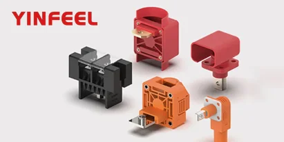
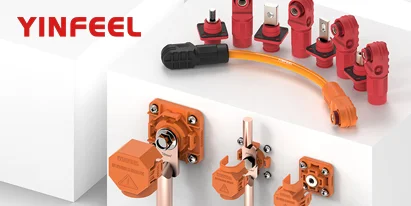
For a comprehensive overview of connector types designed for high-current energy storage applications—including terminal blocks, wall feed-through connectors, and quick-connect terminals—explore the YINFEEL connector product series.
Mistake 1: Using rated current as the design current. The rated current is a maximum under ideal conditions, not a recommended operating current. Always design with margin.
Mistake 2: Ignoring the cable size specified in the derating curve. Derating curves are specific to cable size. Using a smaller cable than the curve assumes invalidates the derating calculation.
Mistake 3: Assuming ambient temperature equals room temperature. Inside an enclosure, ambient temperature can be 20–30°C higher than the surrounding air. Measure or estimate the temperature at the connector location under worst-case conditions.
Mistake 4: Forgetting about multiple energized connectors. Derating curves for single connectors don‘t apply when multiple connectors are packed closely together. Request derating data for your specific configuration.
Mistake 5: Overlooking the 20% safety factor already in the curve. The published derating curve already includes a 20% derating from the test maximum. Applying an additional 20% on top of that is conservative but may be appropriate for critical applications.
Let’s walk through a practical example.
Scenario: You‘re designing a 200A energy storage cabinet. The connector datasheet shows a rated current of 200A at 25°C ambient. The derating curve shows that at 50°C ambient, the maximum safe current drops to approximately 160A (a 20% reduction). You’re using the recommended cable size.
Analysis:
The derated current at 50°C is 160A
Your system requires 200A continuous
The connector is undersized for this application
Solution: Select a connector with a higher rated current—perhaps 250A or 300A—such that the derated value at 50°C exceeds your 200A requirement. Alternatively, improve enclosure cooling to reduce ambient temperature at the connector.
What this means: A 200A-rated connector is not necessarily a 200A connector in your system. Always size up based on your worst-case ambient temperature.
To see how different connector types are applied across residential, commercial, and utility-scale storage scenarios, visit the YINFEEL connectors applications page.
Derating is not an optional extra—it‘s a fundamental requirement for safe and reliable energy storage system design. Start with the worst-case ambient temperature inside your enclosure. Use the manufacturer’s derating curve for your specific cable size and configuration. Read the maximum safe current at that temperature. Then apply an additional guard band for layout variations, aging, and manufacturing tolerances.
Once you‘ve determined the derated current requirement for your application, comparing the specific specifications of available connector families becomes the next logical step. You can evaluate high-current storage terminal connectors designed for 60A–600A applications, or explore wall feed-through terminal blocks for cabinet interconnection—each with different current capacities, temperature rise characteristics, and form factors to match your system’s thermal environment.
For a deeper understanding of how contact resistance, plating materials, and mechanical design affect connector performance under thermal stress, see our related guide on connector performance characteristics.
Understanding UL 4128: Safety Requirements for Energy Storage Connectors
Contact Resistance in High-Current Connectors: Why Milliohms Matter
Thermal Management Strategies for Energy Storage Systems
Cable Sizing for High-Current ESS Applications: What the Standards Say
Connector Plating Materials: Silver vs Tin vs Gold for High-Temperature Environments