Jun 24,2026
Energy Storage Connector Maintenance and Inspection Best Practices

Energy storage connectors are the circulatory system of any battery energy storage system (ESS)—they carry the currents that power homes, businesses, and grid infrastructure. Yet these critical components are often overlooked in routine maintenance programs. The assumption that “if it’s working, it’s fine” is one of the costliest mistakes in energy storage operations.
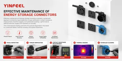
Short answer: Effective maintenance of energy storage connectors requires a systematic approach combining visual inspection, torque verification, contact resistance measurement, thermal imaging, and scheduled cleaning—performed at defined intervals ranging from quarterly to annually. This multi-layered strategy prevents the gradual degradation that leads to connection failure, thermal runaway, and system downtime.
This guide provides a comprehensive maintenance and inspection framework for engineers, facility managers, and maintenance technicians. You will learn what to inspect, how often to inspect it, which tools and methods to use, how to interpret inspection results, and how to build a maintenance schedule that fits your operational requirements.
This is not a generic “keep your connectors clean” article. Here is what makes this guide different:
Specific inspection frequencies — clear, actionable timelines for each maintenance task, backed by industry practice.
Quantifiable acceptance criteria — measurable pass/fail standards for torque, contact resistance, and visual inspection.
Diagnostic decision framework — how to distinguish between oxidation, loosening, and physical damage based on symptoms.
Data recalculation — the real cost of neglected maintenance, expressed in energy waste and dollars.
Comprehensive inspection checklist — a practical tool you can adapt for your own maintenance program.
Definition: Contact resistance is the electrical resistance at the interface between two mating conductive surfaces in a connector. It is measured in milliohms (mΩ) using a micro-ohmmeter with a dry circuit test method (open-circuit voltage ≤20mV) to avoid altering the contact surface.
Why it matters: Contact resistance is the single most important electrical indicator of connector health. Every connection has some inherent contact resistance, but when it increases due to oxidation, contamination, or loosening, it generates heat (Joule heating) that accelerates degradation. Under UL 4128, the acceptable contact resistance for energy storage connectors is ≤0.5mΩ. When resistance exceeds this threshold, power loss increases and the connection becomes a potential failure point.
Common mistake: Measuring contact resistance with the system energized or with a standard multimeter. Proper contact resistance measurement requires a micro-ohmmeter using a dry circuit (low voltage, low current) to avoid breaking through oxide films and giving falsely low readings.
Decision impact: Contact resistance should be measured at least annually on critical connections, and any reading exceeding the manufacturer’s specification (typically >0.5mΩ for UL 4128-rated connectors) should trigger cleaning or replacement.
Definition: Torque specification is the manufacturer-recommended tightening force, expressed in Newton-meters (Nm), applied to threaded connections such as bolt-type terminals. It ensures proper mechanical clamping force without damaging the connector or conductor.
Why it matters: Proper torque is critical for maintaining low contact resistance and preventing loosening under vibration and thermal cycling. Insufficient torque leads to loose connections, high resistance, and overheating. Excessive torque can deform terminals, strip threads, or damage conductor strands. For high-voltage energy storage interfaces, typical torque specifications are around 9.5 Nm.
Common mistake: Using a standard wrench instead of a calibrated torque wrench, or relying on “feel” rather than a measured value. This is one of the most frequent causes of connection failure.
Decision impact: Every maintenance program must include torque verification using a calibrated torque wrench. Torque should be checked at installation, during quarterly inspections, and after any maintenance that involves loosening a connection.
Before designing or implementing a connector maintenance program, answer these five questions:
What type of connectors are in your system? — Threaded bolt-type, quick-connect, or plug-in/pull-out connectors have different maintenance requirements and failure modes.
What is the operating environment? — Temperature extremes, humidity, dust, vibration, and outdoor exposure all affect maintenance frequency.
What are the system’s criticality and uptime requirements? — Mission-critical systems require more frequent inspection and predictive maintenance.
What tools and equipment are available? — Torque wrenches, micro-ohmmeters, thermal cameras, and cleaning supplies must be on hand.
What standards apply? — UL 4128, IEC 61984, or other regional requirements may dictate specific test methods and acceptance criteria.
For application-specific considerations, <a href="/applications">explore application scenarios</a>.
A robust connector inspection program incorporates multiple inspection methods applied at defined frequencies.
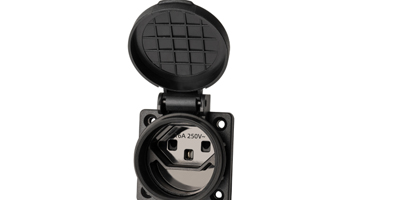
Visual inspection is the first line of defense. It requires no specialized equipment and can catch problems before they escalate.
What to check:
Housing cracks, deformation, discoloration, or melting — signs of overheating or mechanical stress
Corrosion, rust, or white oxidation on metal surfaces
Bent, broken, or loose pins and sockets
Locking mechanism integrity — latches should engage and disengage smoothly
Cable insulation — check for thermal degradation, cracking, or brittleness
Seal and O-ring condition — cracks or deformation compromise IP rating
How to judge: Housing should show no cracks visible to the naked eye. According to IEC 61984 safety requirements, heavy-duty connector shells must show zero visible micro-cracks under 5× magnification during routine evaluation. Discoloration (bluing, browning, blackening) indicates overheating and requires immediate investigation.
What to avoid: Skipping visual inspection because “it looks fine from a distance.” Close inspection with good lighting is essential.
Electrical testing provides quantitative data on connector health.
Contact Resistance Measurement:
Use a micro-ohmmeter with dry circuit test method (open-circuit voltage ≤20mV)
Measure resistance across each mated connector pair
Compare readings against manufacturer specification (typically ≤0.5mΩ for UL 4128-rated connectors)
Insulation Resistance Test:
Use a megohmmeter (high-resistance meter) to measure insulation resistance between contacts and between contacts and ground
Typical acceptable value: ≥5000MΩ (from the provided HTML code’s technical parameters)
Perform annually or after any maintenance that could compromise insulation
Continuity Test:
Verify electrical continuity through each connector path
Perform before re-energizing after any maintenance that involves disconnection
How to judge: Contact resistance exceeding manufacturer specification by more than 20% warrants investigation. Any insulation resistance below specification indicates insulation damage requiring immediate replacement.
Threaded connections require regular torque verification to prevent loosening from thermal cycling and vibration.
What to do: Use a calibrated digital torque wrench to verify that all bolted connections meet the manufacturer‘s torque specification.
Why it matters: Thermal cycling causes expansion and contraction of dissimilar metals, which can gradually loosen connections over time. Vibration in mobile or industrial applications accelerates this process.
How to judge: Torque readings should match the manufacturer’s specification, typically around 9.5 Nm for high-voltage interfaces. If torque is below specification, re-tighten to the correct value. If torque is consistently below specification, investigate whether the connection hardware needs replacement.
Common mistake: Overtightening to “make sure it’s secure.” Over-tightening can warp metal tabs, strip threads, or damage conductor strands.
Infrared thermography is one of the most powerful non-invasive diagnostic tools for connector maintenance.
What to do: Use a thermal imaging camera to scan all connector connections during peak load operation.
Why it matters: Heat is the primary enemy of electrical interfaces. A connection that is running hotter than surrounding connections of the same type almost certainly has elevated contact resistance.
How to judge: Under UL 4128, the temperature rise at the electrical connection shall not exceed 45°C (45K) when tested at rated current for 4 hours or until thermal stability is reached. In practical field inspection, compare the temperature of each connection against:
The manufacturer’s maximum temperature rating
The temperature of similar connections in the same system
Historical temperature data from previous inspections
What to avoid: Performing thermal imaging when the system is not under load. Connections only generate detectable heat when current is flowing.
To understand the full quality control framework, review the quality control process.
Contaminated contact surfaces are a primary cause of increased contact resistance.
At least annually for all contact surfaces
More frequently in dusty, humid, or corrosive environments
Immediately if visual inspection reveals oxidation or debris
For light contamination:
Spray contacts with filtered air or inert gas to remove loose particle contamination
Use a soft bristle brush to remove stubborn particles
For oxidation or heavy contamination:
Apply specialized electrical contact cleaners to remove non-conductive oxide layers
Use 99% pure isopropyl alcohol applied to a soft brush or lint-free cloth
Ensure complete drying before re-mating the connector
What to avoid:
Never use corrosive substances or sharp objects that could damage the contact surface
Never use wet cloths or chemical solvents that could leave residue or cause corrosion
Never clean contacts with abrasive materials that remove the plating
After cleaning, consider applying:
Protective lubricants: High-temperature synthetic grease can seal the interface against moisture and future atmospheric corrosion
Dust covers: Use protective caps on exposed connectors when not in use
Environmental sealing: Confirm O-rings are seated correctly to prevent ingress during outdoor operations
Understanding why connectors fail helps target maintenance efforts effectively.
Symptoms: Sudden or intermittent resistance spikes, physical gaps visible under microscopic inspection, instantaneous voltage drops during high-current discharge
Root causes:
Insufficient initial torque during installation
Vibration in mobile or industrial applications
Thermal cycling causing expansion/contraction of dissimilar metals
Creep in softer materials (e.g., aluminum)
Remediation: Re-torque to manufacturer specification, typically around 9.5 Nm
Symptoms: Gradual resistance increase over time, discoloration or film formation on contact surfaces, consistent baseline resistance elevation across multiple test cycles
Root causes:
Exposure to moisture, salts, or corrosive atmospheres
Galvanic corrosion between dissimilar metals (e.g., copper busbar to aluminum terminal)
Contamination by dust or dirt increasing surface resistance
Remediation: Clean with approved electrical contact cleaner; if oxidation is severe, consider contact replacement
Symptoms: Visible cracks, deformation, bent pins, melted insulation
Root causes:
Mechanical stress during handling or maintenance
Overtightening causing terminal deformation or thread stripping
Impact damage or stress fractures from vibration
Remediation: Replace damaged components immediately
Symptoms: Discoloration (bluing, browning, blackening), melted insulation, deformation of plastic components
Root causes:
Loose connections (mechanical loosening)
Corrosion increasing resistance
Overload beyond rated current
Remediation: Replace affected connectors and address root cause
When contact resistance increases due to poor maintenance, the system wastes energy as heat. Here is the impact.
Given:
System current: 200A (typical for large energy storage connectors)
New connector contact resistance: 0.5mΩ (per UL 4128 specification)
Degraded connector contact resistance: 1.5mΩ (three times specification—common after 1-2 years without maintenance)
Calculation:
Power loss (new): P = I² × R = 200² × 0.0005 = 20W per connection
Power loss (degraded): P = 200² × 0.0015 = 60W per connection
Additional loss per connection: 40W
For a typical ESS with 20 connector pairs, if all are degraded:
Total additional loss: 40W × 20 = 800W
Annual energy waste: 0.8kW × 8,760 hours = 7,008 kWh/year
At $0.15/kWh: **$1,051/year in wasted energy**
Interpretation:
This calculation does not include the cost of accelerated component aging, the risk of unplanned downtime, or the potential for catastrophic failure. A single morning of maintenance per year—cleaning contacts and verifying torque—can prevent this waste and extend system life.
Decision takeaway:
Investing in a regular maintenance program is not an expense—it is an investment that typically pays for itself many times over through reduced energy waste, extended equipment life, and avoided downtime.
What it covers: UL 4128 is the primary safety standard for energy storage connectors used in battery energy storage systems. It covers connectors rated up to 2000Vdc. Key requirements include temperature rise (≤45°C at rated current), contact resistance (≤0.5mΩ), and IP67 protection when mated.
Why it matters for maintenance: UL 4128 certification provides baseline performance criteria that maintenance programs should reference. If a connector is UL 4128-certified, its temperature rise and contact resistance specifications define acceptable maintenance limits.
Decision implication: When performing maintenance, verify that contact resistance and temperature rise remain within UL 4128 limits. If they exceed specification, the connector requires cleaning or replacement.
What it covers: IEC 61984 applies to connectors with rated voltages above 50V and up to 1000V, with rated currents up to 125A per contact. It specifies safety requirements including clearance and creepage distances.
Why it matters for maintenance: During routine maintenance evaluation, connectors must show zero visible micro-cracks under 5× magnification. This provides a clear, measurable acceptance criterion for visual inspection.
Decision implication: Include 5× magnification inspection in your maintenance procedure for critical connectors.
What it covers: This standard details a test method to assess the ability of a connector to withstand stresses caused by repeated extraction and insertion of contacts during maintenance.
Why it matters for maintenance: Connectors that are frequently disconnected and reconnected during maintenance are subject to contact wear and seal degradation. This standard provides a framework for understanding the durability limits of connector systems.
Decision implication: For connectors that require frequent disconnection for maintenance, verify the manufacturer‘s rated durability cycles and track the number of mating cycles to avoid exceeding the design limit.
What it covers: This Chinese standard specifies technical requirements for connection devices between energy storage battery modules, including environmental testing at 100°C for 400 hours and thermal shock testing.
Why it matters for maintenance: Understanding the environmental rating of connectors helps determine appropriate maintenance frequencies for different operating conditions.
Decision implication: Connectors installed in high-temperature environments (e.g., outdoor enclosures in hot climates) require more frequent inspection than those in climate-controlled indoor settings.
What to do: Document contact resistance, torque values, and thermal images for all critical connections when the system is new or after major maintenance.
Why it matters: Baseline data provides the reference point for detecting degradation. A 20% increase from baseline is a warning sign.
How to judge: Record all measurements in a maintenance log with dates and operating conditions.
Avoid: Skipping baseline documentation because “it’s working fine.”
What to do: Create a maintenance schedule based on connector type and operating environment.
| Component | Frequency | Action |
|---|---|---|
| Visual inspection | Every 1-3 months | Check for cracks, corrosion, discoloration |
| Locking latches | Every 6 months | Check for mechanical fatigue |
| Cable insulation | Every 6 months | Inspect for thermal degradation |
| Torque verification | Every 6 months | Verify all threaded connections |
| Contact surfaces | Every 12 months | Remove oxidation or debris |
| Sealing rings | Every 24 months | Replace to maintain IP rating |
Why it matters: Scheduled inspections catch problems before they cause failures.
How to judge: Adjust frequency based on operating conditions—more frequent in harsh environments.
Avoid: Waiting for a failure before inspecting.
What to do: Use a micro-ohmmeter with dry circuit method to measure contact resistance across all critical connections.
Why it matters: Contact resistance is the most direct electrical indicator of connector health.
How to judge: Pass if ≤0.5mΩ (UL 4128). Investigate if >0.5mΩ. Replace if >1.0mΩ.
Avoid: Using a standard multimeter, which cannot accurately measure milliohm-level resistance.
What to do: Scan all connections with a thermal imaging camera during peak system operation.
Why it matters: Thermal imaging identifies hot spots that indicate high resistance before they cause failure.
How to judge: Any connection more than 10°C hotter than similar connections warrants investigation. Temperature rise should not exceed 45°C per UL 4128.
Avoid: Performing thermal imaging when the system is not under load.
What to do: Clean contacts annually (or more frequently in harsh environments) using approved methods and materials.
Why it matters: Clean contacts maintain low resistance and prevent oxidation-induced degradation.
How to judge: Contact surfaces should be bright and free of visible oxidation or debris after cleaning.
Avoid: Using abrasive materials or corrosive solvents.
What to do: Maintain a comprehensive maintenance log with all inspection results, measurements, and actions taken.
Why it matters: Trend data reveals gradual degradation before it reaches failure thresholds.
How to judge: Compare current measurements against baseline and previous readings.
Avoid: Treating each inspection as an isolated event.
To understand connector selection that minimizes maintenance requirements, explore the complete connector product series.
Key priorities:
Weatherproofing and corrosion prevention
More frequent inspection (moisture, temperature extremes)
Thermal imaging during seasonal peak loads
Common risk: Moisture ingress and galvanic corrosion between dissimilar metals.
Decision logic: Increase inspection frequency to monthly visual checks. Use sealed connectors with IP67 or higher rating. Apply protective grease to all contact surfaces. Inspect seals and O-rings every 12 months rather than 24.
Related reading: explore application scenarios
Key priorities:
Regular torque verification (thermal cycling from daily charge/discharge)
Contact resistance monitoring
Dust prevention
Common risk: Gradual loosening from thermal cycling and dust accumulation on contacts.
Decision logic: Follow standard maintenance schedule. Pay special attention to connections near heat-generating equipment. Use dust covers on unused ports.
Related reading: review storage quick connection terminal bolt options
Key priorities:
Frequent torque verification
Vibration-resistant locking mechanisms
Strain relief inspection
Common risk: Connection loosening from vibration and mechanical stress.
Decision logic: Increase torque verification to quarterly. Use connectors with secondary locking features. Inspect strain relief and cable anchoring points regularly.
Related reading: review plug-in pull-out mating type series
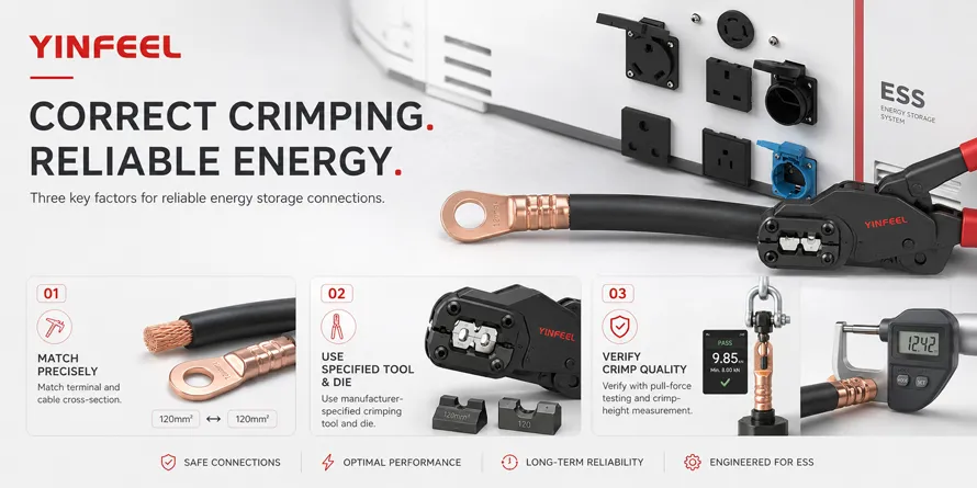
Field observation: In one large-scale ESS project, over 60% of field returns were traced to improper crimping and inadequate maintenance rather than connector design defects. The most common issue was loose bolted connections that had not been re-torqued after initial thermal cycling.
What it means: Most connector failures are preventable through proper installation and regular maintenance. The connector itself is rarely the root cause.
Practical takeaway: Always re-torque bolted connections after the first 24-48 hours of operation and again after the first major thermal cycle. This catches the initial settling that occurs as materials expand and contract.
Common maintenance mistake: Assuming that “visual inspection is enough.” In one documented case, a connection that appeared visually perfect had contact resistance over 2.0mΩ—four times the UL 4128 specification—due to invisible oxidation between mating surfaces.
What it means: Visual inspection must be complemented with electrical and thermal measurements. You cannot see resistance.
Practical takeaway: Invest in a micro-ohmmeter and thermal camera. These tools pay for themselves in prevented downtime.
Industry observation: Connectors in systems with regular preventive maintenance programs last 2-3 times longer than those in “run-to-failure” systems. The maintenance cost is typically less than 5% of the cost of an unplanned outage.
What it means: Preventive maintenance is not just good engineering—it is good economics.
Practical takeaway: Build the business case for maintenance using the data recalculation example above. Show your management that maintenance saves money.
Regular maintenance of energy storage connectors is essential because degraded connections increase contact resistance, which generates heat and wastes energy. A connection with three times the specified contact resistance wastes 40W of power at 200A—equivalent to over $1,000 in annual energy loss per 20-connection system. More critically, overheating connections can lead to insulation failure, thermal runaway, and system downtime.
Energy storage connectors should undergo visual inspection every 1-3 months, torque verification and cable insulation inspection every 6 months, and contact surface cleaning and resistance measurement annually. In harsh environments (outdoor, high humidity, high vibration), inspection frequencies should be increased.
The most common cause of connector failure is loosening of bolted connections due to thermal cycling and vibration. This creates high-resistance connections that generate heat, leading to a cycle of degradation. The second most common cause is contact surface oxidation from moisture exposure.
Essential tools for connector maintenance include a calibrated torque wrench for verifying bolt tightness, a micro-ohmmeter for contact resistance measurement, a thermal imaging camera for detecting hot spots, and approved electrical contact cleaner for removing oxidation. A magnifying glass or 5× microscope is useful for detailed visual inspection.
UL 4128 does not specify maintenance frequencies, but it does establish performance limits that maintenance programs should verify: contact resistance ≤0.5mΩ and temperature rise ≤45°C at rated current. Maintenance programs should ensure that connectors remain within these limits throughout their service life.
Q1: How often should energy storage connectors be inspected? Inspection frequency depends on connector type and operating environment. As a general guideline: visual inspection every 1-3 months, torque verification every 6 months, contact surface cleaning and resistance measurement annually. Harsh environments require more frequent inspection.
Q2: What are the signs that a connector needs maintenance? Key warning signs include: visible discoloration or melting on the housing, corrosion or oxidation on contact surfaces, loose locking mechanisms, elevated operating temperature (detected by thermal imaging), and contact resistance above manufacturer specification.
Q3: How do you clean energy storage connector contacts? Use filtered air or inert gas to remove loose particles, then a soft bristle brush with 99% isopropyl alcohol for stubborn contamination. For oxidation, apply specialized electrical contact cleaner. Never use abrasive materials or corrosive solvents.
Q4: What torque should be applied to energy storage connector bolts? Torque specifications vary by connector type and size. For high-voltage energy storage interfaces, typical torque is around 9.5 Nm. Always refer to the manufacturer‘s specific torque specification and use a calibrated torque wrench.
Q5: How does contact resistance affect system performance? Elevated contact resistance wastes energy as heat. At 200A, every 1mΩ of excess resistance wastes 40W of power. Over a year, this can translate into thousands of dollars in wasted energy and accelerated component aging.
Q6: When should a connector be replaced rather than repaired? Replace connectors when: contact resistance exceeds 1.0mΩ and cleaning does not restore it, housing shows cracks or melting, locking mechanisms are broken, seals are damaged, or the connector has exceeded its rated durability cycles.
The most reliable way to ensure long-term performance of energy storage connectors is to follow a systematic maintenance program based on three core principles: inspect regularly (visual, thermal, and electrical checks at defined intervals), measure quantitatively (contact resistance, torque, and temperature against defined limits), and act promptly (clean, re-torque, or replace when measurements exceed thresholds).
Three core decision dimensions:
Frequency — How often should each type of inspection be performed? (Match frequency to environment and criticality.)
Method — Are you using the right tools and techniques for each inspection type?
Threshold — What are your pass/fail criteria for each measurement?
Final takeaway: A connector that is working today may be failing tomorrow. Regular, systematic maintenance is not optional—it is essential for system safety, efficiency, and longevity. The cost of maintenance is small compared to the cost of failure.
For a broader understanding of connector quality and manufacturing, review the quality control process.
This article is for informational and educational purposes. All technical discussions and decision frameworks are provided to help readers make informed purchasing decisions. No direct sales, pricing, or promotional information is included. — YINGFEI ELECTRICAL
Energy Storage Connector Selection Guide: How to Choose the Right Connector for Your ESS
Common Failure Modes of Energy Storage Connectors and How to Prevent Them
Contact Resistance in High-Current Connectors: Measurement and Interpretation
Understanding UL 4128: Certification Requirements for Energy Storage Connectors
How to Crimp Energy Storage Connectors Correctly: A Step-by-Step Guide