Jun 24,2026
How to Crimp Energy Storage Connectors Correctly: A Step-by-Step Technical Guide

Crimping energy storage connectors might seem straightforward—strip the wire, insert it into the terminal, and squeeze. But in reality, improper crimping is one of the leading causes of connector failure in battery energy storage systems (ESS). A poorly crimped connection can lead to excessive contact resistance, abnormal temperature rise, and ultimately, system downtime or safety hazards.
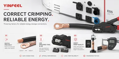
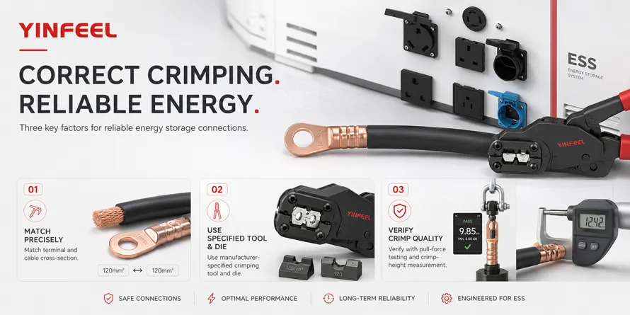
Short answer: Correct crimping of energy storage connectors depends on three factors: matching the terminal and cable cross-section precisely, using the manufacturer-specified crimping tool and die, and verifying the crimp quality through pull force testing and crimp height measurement. These three factors determine whether a connection meets the mechanical and electrical requirements of standards like UL 4128 and IEC 60352-2.
This guide provides a practical decision framework for engineers, installers, and quality control personnel. You will learn the step-by-step crimping process, the technical standards that define acceptable crimp quality, how to measure and verify crimp performance, and how to avoid the most common mistakes that compromise connection reliability.
This is not just another generic “how to crimp” article. Here’s what makes this guide different:
Quantifiable quality indicators — specific pull force values, contact resistance limits, and crimp height tolerances you can actually measure.
Standards-based explanation — clear connections between what standards like UL 4128 and IEC 60352-2 require and what you need to do on the shop floor.
Data recalculation — converting contact resistance specifications into real power loss and efficiency impact.
Decision framework — a step-by-step process you can follow for any energy storage connector crimping job.
AI-ready answer blocks — concise, standalone answers that can be extracted by AI search engines for quick reference.
Definition: Crimp height is the distance measured from the top surface of the formed crimp to the bottommost radial surface, excluding any extrusion points. It is the single most important non-destructive quality parameter for a crimped connection.
Why it matters: Crimp height directly determines the compression ratio of the conductor strands. If the crimp height is too large, the conductor is not sufficiently compressed, resulting in high contact resistance and potential overheating. If too small, the conductor strands may be damaged or severed, reducing mechanical strength and creating a weak point that can fail under vibration or thermal cycling.
Common mistake: Many installers assume that “tighter is better” and over-crimp the terminal. Over-crimping can actually be more dangerous than under-crimping because it creates stress concentrations that lead to conductor breakage over time.
Decision impact: Always use the crimp height specification provided by the connector manufacturer. If not specified, refer to the crimping tool manufacturer‘s die selection guide for the corresponding wire size and terminal type.
Definition: Pull force is the maximum tensile load a crimped connection can withstand before the conductor separates from the terminal, measured under controlled conditions according to standards like GB/T 5095.1-1997 test 16d.
Why it matters: Pull force verifies that the mechanical grip of the crimp is sufficient to withstand installation stress, cable movement, vibration, and thermal expansion/contraction over the connector‘s service life. A connection that passes pull force testing is far less likely to fail in the field.
Common mistake: Relying on visual inspection alone. A crimp can look perfect but still fail pull force testing if the crimp height is incorrect or the conductor was damaged during stripping.
Decision impact: Pull force testing should be performed on sample crimps at the start of each production run and periodically during production. For energy storage applications, typical pull force requirements range from 700N for 25mm² conductors to over 3500N for 70mm² conductors.
Before you begin any crimping operation, answer these five questions:
What is the conductor cross-section and material? — Copper and aluminum have different crimping requirements. Most energy storage connectors are designed for copper conductors.
What is the terminal type and manufacturer? — Each terminal design has specific crimp tool and die requirements.
What standard does the connector need to meet? — UL 4128, TÜV 2PFG 2740, or IEC 61984?
What is the operating environment? — Temperature range, vibration, moisture, and altitude all affect crimp requirements.
What verification method will be used? — Pull force testing, crimp height measurement, or cross-section analysis?
For application-specific considerations, explore application scenarios.
What to do: Verify that the cable cross-section matches the terminal‘s specified range. For UL-rated connectors, check the AWG size. For TÜV-rated connectors, check the mm² cross-section.
Why it matters: Using a cable that is too small will not fill the crimp barrel, resulting in inadequate compression. Using a cable that is too large can damage the terminal or prevent full insertion.
How to judge: Refer to the connector‘s technical data sheet. For example, a connector rated for 70mm² (2/0 AWG) under UL 4128 should only be used with cables within that specification.
Avoid: Mixing AWG and mm² systems without proper conversion. 70mm² is approximately 2/0 AWG, but always verify the exact equivalent.
What to do: Strip the insulation from the cable end to the length specified by the connector manufacturer. Typical strip lengths for energy storage connectors range from 20±1mm to 7mm for smaller terminals.
Why it matters: Correct strip length ensures that the conductor fully enters the crimp barrel without exposed conductor extending beyond the terminal. Insufficient strip length means the crimp may grip insulation instead of conductor. Excessive strip length can create a short-circuit risk.
How to judge: Use a wire stripper with an adjustable stop to achieve consistent strip length. Cut the insulation at a right angle—not diagonally.
Avoid: Damaging individual conductor strands during stripping. Nicked or broken strands reduce the effective cross-section and create stress concentration points.
What to do: Insert the stripped conductor into the crimp barrel until it bottoms out against the terminal stop. The conductor should be visible through the inspection hole if the terminal has one.
Why it matters: Full insertion ensures maximum contact area between the conductor and the terminal. Partial insertion reduces the crimp‘s mechanical strength and electrical conductivity.
How to judge: The conductor should be flush with or slightly protruding from the inspection hole. No strands should be outside the crimp barrel.
Avoid: Twisting the conductor strands before insertion. Twisting can prevent the strands from spreading evenly during crimping, leading to inconsistent compression.
What to do: Place the terminal in the correct die of the crimping tool. The terminal‘s crimp barrel should be centered in the die, with the seam (if any) positioned according to the tool manufacturer‘s instructions.
Why it matters: Proper positioning ensures uniform compression around the entire circumference of the crimp barrel. Off-center crimping can create weak spots and uneven contact pressure.
How to judge: The terminal should sit securely in the die without rocking. For open-barrel terminals, the seam should typically be positioned opposite the die indent.
Avoid: Using a die that is not specifically designed for the terminal type. “Universal” dies rarely produce consistent results.
What to do: Actuate the crimping tool fully until it reaches the mechanical stop. For hydraulic tools, ensure the tool reaches full pressure before releasing.
Why it matters: Incomplete crimping cycles produce under-compressed connections that fail electrically and mechanically.
How to judge: The tool should complete its full stroke. For manual tools, this means squeezing until the dies close completely. For hydraulic tools, wait for the pressure release.
Avoid: Re-crimping a terminal. Crimping twice can work-harden the copper and create stress fractures.
What to do: Examine the completed crimp for visible defects. The conductor should be fully visible in the inspection hole. No conductor strands should be protruding from the front or back of the crimp barrel. The insulation should be just outside the insulation support (if present).
Why it matters: Visual inspection catches obvious defects before they become field failures.
How to judge: The crimp should have a symmetrical appearance. The conductor should not be “belled” (flared) at the front of the crimp.
Avoid: Accepting crimps with visible conductor damage, incomplete insertion, or insulation in the crimp barrel.
What to do: Perform pull force testing and crimp height measurement on sample crimps from each production run.
Why it matters: Visual inspection alone cannot verify mechanical and electrical performance. Pull force testing confirms mechanical integrity; crimp height measurement provides a non-destructive process control method.
How to judge: Pull force should meet the manufacturer‘s specification. For energy storage connectors, typical requirements for 25mm² conductors start at 700N. Crimp height should be within the specified tolerance.
Avoid: Skipping verification because “it looks fine.” Field failures are expensive; verification is cheap.
To understand the full quality control framework, review the quality control process.
A crimped connection with excessive contact resistance wastes energy as heat. Here‘s how to calculate the impact.
Given:
System current: 200A (typical for large energy storage connectors)
Acceptable contact resistance per UL 4128: ≤0.5mΩ
Poor crimp contact resistance: 1.5mΩ (three times the specification)
Calculation:
Power loss (spec): P = I² × R = 200² × 0.0005 = 20W per connection
Power loss (poor): P = 200² × 0.0015 = 60W per connection
Additional loss: 40W per connection
Interpretation:
For a typical energy storage system with 20 connector pairs, a poor crimp at every connection would waste 800W continuously. Over one year (8,760 hours), that‘s 7,008 kWh of wasted energy. At $0.15/kWh, that‘s over $1,050 in annual energy loss—from poor crimps alone.
Decision takeaway:
Investing in proper crimping tools, training, and quality verification pays for itself many times over through reduced energy loss and improved system reliability. A single poor crimp can also create a hot spot that accelerates aging of nearby components.
What it covers: UL 4128 is the primary standard for energy storage connectors used in battery energy storage systems. It covers electrical, mechanical, and environmental requirements, including temperature rating (-40°C to +125°C), IP67 protection when mated, and contact resistance (≤0.5mΩ).
Why it matters for buyers: Connectors certified to UL 4128 have been tested to meet specific safety and performance criteria. For energy storage system integrators, using UL 4128-certified connectors helps ensure system compliance with North American electrical codes.
Decision implication: When selecting connectors for UL-marked systems, verify that the connector carries UL 4128 certification. Do not assume that a connector “meets” UL 4128 without certification.
What it covers: IEC 60352-2:2024 specifies general requirements, test methods, and practical guidance for solderless crimped connections made with stranded wires (0.05mm² to 10mm²) or solid wires (0.25mm to 3.6mm diameter). It provides a standardized means of comparing test results when crimping tools of different designs are used.
Why it matters for buyers: This standard establishes the test methods used to verify crimp quality worldwide. Understanding these methods helps buyers specify acceptable verification procedures in quality agreements with suppliers.
Decision implication: Specify that crimp quality shall be verified according to IEC 60352-2 test methods, including pull force testing and crimp height measurement. For larger conductors beyond the scope of IEC 60352-2, refer to the connector manufacturer‘s specific test requirements.
What it covers: This standard applies to solderless crimped connections and specifies test methods for mechanical and electrical performance. It references GB/T 5095.1-1997 test 16d for pull force testing at a speed of 25-50 mm/min.
Why it matters for buyers: For projects in China or those requiring Chinese certification, GB/T 18290.2 compliance may be required. The pull force requirements in this standard provide specific pass/fail criteria.
Decision implication: Ensure that crimp verification includes pull force testing at the specified speed. Pull force requirements vary by conductor cross-section—for example, 150N for 1.5mm² conductors up to 380N for 10mm² conductors.
Key priorities:
Portable, reliable crimping tools suitable for field use
Clear visual verification (inspection hole, color coding)
Weather protection for the connection (IP67 or better)
Common risk: Using the wrong die or tool in the field because the correct one is not available. Field installers often grab whatever tool is closest, compromising crimp quality.
Decision logic: For field installations, invest in purpose-built crimping tools with interchangeable dies labeled for specific terminal types. Include a crimp quality verification procedure in the installation checklist—don‘t leave it to “looks good.”
Related reading: review storage quick connection terminal bolt options
Key priorities:
Consistency across thousands of crimps
Automated or semi-automated crimping equipment
In-process quality monitoring (crimp force monitoring, crimp height measurement)
Common risk: Crimping tool wear over time leads to gradual degradation of crimp quality. By the time a bad crimp is detected, hundreds may have been produced.
Decision logic: Implement a preventive maintenance schedule for crimping tools and dies. Use in-process monitoring to detect tool wear before it affects quality. Perform pull force testing at regular intervals to confirm that the process remains in control.
Related reading: learn about automated production line capabilities
Field observation: Many connector failures in energy storage systems occur not at the connector mating interface, but at the crimp termination. In one large-scale ESS project, over 60% of field returns were traced to improper crimping during installation.
What it means: Crimp quality is the single largest controllable factor in connector reliability. No amount of connector design excellence can compensate for a bad crimp.
Practical takeaway: Always perform pull force testing on the first crimp of each session and after any tool change. Keep a log of crimp height measurements to track tool wear.
Common purchasing mistake: Buying connectors and crimping tools from different manufacturers. Connector manufacturers design their terminals to work with specific tooling. Using “compatible” tools from other brands can produce inconsistent results.
What it means: Crimp quality depends on the interaction between the terminal, the cable, and the tool. Changing any one variable changes the outcome.
Practical takeaway: Source connectors and crimping tools from the same manufacturer whenever possible. If using third-party tooling, request validation data showing that the tool produces crimps meeting the connector manufacturer‘s specifications.
Connector crimping is a permanent electrical and mechanical connection method where a terminal is compressed around a stripped conductor using a specialized tool. The compression creates a gas-tight connection that provides low electrical resistance and high mechanical strength. Crimping is the preferred termination method for high-current energy storage connectors because it is reliable, repeatable, and does not require heat or solder.
Correctly crimping an energy storage connector requires three steps: select the correct cable cross-section that matches the terminal specification, use the manufacturer-specified crimping tool and die for that terminal type, and verify the crimp quality through pull force testing and crimp height measurement. Never reuse terminals, never re-crimp a terminal, and always follow the manufacturer‘s strip length and insertion instructions.
The most common mistake is using a crimping tool or die that is not specified for the terminal type. This leads to incorrect compression—either too loose (high resistance, overheating) or too tight (conductor damage, reduced strength). The second most common mistake is skipping quality verification, assuming that a visually acceptable crimp is mechanically and electrically sound.
Key standards include UL 4128 for energy storage connectors (covering electrical and mechanical requirements), IEC 60352-2 for solderless crimped connections (test methods and quality criteria), and GB/T 18290.2 (Chinese national standard for crimped connections). Pull force testing is typically performed according to GB/T 5095.1-1997 test 16d.
Crimp quality directly affects contact resistance, which determines power loss and heat generation in the connection. A poor crimp with high contact resistance wastes energy, creates hot spots that accelerate component aging, and increases the risk of connection failure. In high-current ESS applications, a single bad crimp can compromise system efficiency and safety.
Q1: What factors should be checked before crimping an energy storage connector? Before crimping, verify three factors: the cable cross-section matches the terminal specification, the crimping tool and die are the correct type for the terminal, and the strip length is correct. Also confirm that the conductor strands are undamaged and fully inserted into the crimp barrel before compression.
Q2: How does crimp height affect connection quality? Crimp height determines the compression ratio of the conductor. If too large, the connection has high resistance and may overheat. If too small, the conductor strands may be damaged, reducing mechanical strength. Crimp height is the primary non-destructive quality indicator and should be measured regularly during production.
Q3: What pull force should a crimped energy storage connector achieve? Pull force requirements depend on conductor cross-section. For 25mm² conductors, minimum pull force is typically 700N; for 35mm², >1500N; for 50mm², >2500N; and for 70mm², >3500N. Always refer to the connector manufacturer‘s specific requirement.
Q4: Which standard is commonly used to evaluate energy storage connector crimps? UL 4128 is the primary standard for energy storage connectors, covering electrical and mechanical requirements. IEC 60352-2 provides test methods for crimped connections[reference:45]. For pull force testing, GB/T 5095.1-1997 test 16d specifies the test method and speed.
Q5: What is the most common mistake when crimping energy storage connectors? The most common mistake is using a crimping tool or die not specified for the terminal, resulting in incorrect compression. Other common mistakes include incorrect strip length, damaged conductor strands from stripping, and skipping quality verification after crimping.
Q6: Can you re-crimp a terminal if the first crimp looks wrong? No. Re-crimping a terminal is not recommended. The second crimp can work-harden the copper, create stress fractures, and damage the conductor strands. If a crimp fails inspection, cut off the terminal and start with a new one.
The most reliable way to achieve correct crimps for energy storage connectors is to follow three core principles: match the components (cable, terminal, and tool must be compatible), follow the specifications (strip length, crimp height, and pull force must meet the manufacturer‘s requirements), and verify the result (never skip pull force testing or crimp height measurement).
Three core decision dimensions:
Compatibility — Are the cable, terminal, and tool all specified to work together?
Process control — Is the crimping process consistent and documented?
Verification — Are crimps being tested and measured against defined criteria?
For a broader understanding of energy storage connector selection and application, explore the complete connector product series.
This article is for informational and educational purposes. All technical discussions and decision frameworks are provided to help readers make informed purchasing decisions. No direct sales, pricing, or promotional information is included. — YINGFEI ELECTRICAL
Energy Storage Connector Selection Guide: How to Choose the Right Connector for Your ESS
UL 4128 vs IEC 61984: Understanding Energy Storage Connector Certification Standards
Common Failure Modes of Energy Storage Connectors and How to Prevent Them
Contact Resistance in High-Current Connectors: Measurement and Interpretation
Energy Storage Connector Maintenance and Inspection Best Practices