Jul 15,2026
Common Failure Modes of Energy Storage Connectors and How to Prevent Them

Your energy storage system’s battery management system monitors voltage, current, and temperature across thousands of data points. Yet when a connector fails—melting insulation, generating arcs, or triggering thermal runaway—it often happens before the BMS registers a fault. The failure is mechanical, not electronic. And it can cost millions in asset losses.
This guide examines the most common failure modes in energy storage connectors—loose connections, overheating, corrosion, vibration damage, and improper installation—and provides practical prevention strategies for each.
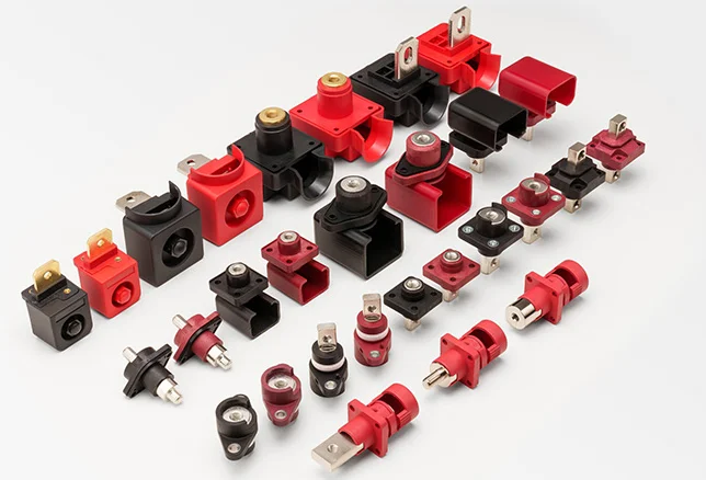
Connectors are the critical junctions where electrical energy flows between battery modules, racks, and power conversion systems. A single weak link can create a high-resistance point, generate localized heat through Joule heating (I²R), and escalate from a minor degradation to a catastrophic failure.
The challenge is that connector degradation is often invisible to digital monitoring. Localized contact resistance spikes and micro-vibrations generate intense heat that can melt terminal insulation before software diagnostics detect anything unusual. By the time the system registers a fault, the damage is already done.
Understanding how and why connectors fail is the first step toward preventing those failures.
What happens: Loose connections are the most common connector problem in energy storage systems. They occur when insufficient torque is applied during assembly, when vibration gradually backs out locking mechanisms, or when thermal cycling causes dissimilar metals to expand and contract at different rates.
Why it matters: A loose connection increases resistance exponentially. At currents of hundreds of amperes, even a small increase in resistance generates significant heat. This heat accelerates further degradation, creating a feedback loop that can lead to insulation melting, arcing, and fire.
How to detect: Intermittent voltage drops, localized hot spots visible on thermal imaging, and contact resistance readings exceeding 0.5 milliohms are all warning signs.
Prevention:
Use calibrated torque wrenches to tighten all fasteners to equipment specifications
Deploy secondary locking clips or positive locking mechanisms that absorb vibration and keep connectors seated
Apply torque marking to visually confirm that fasteners haven’t moved
What happens: Overheating is the primary failure mode in high-current connectors. It stems from surface oxidation (which creates a film resistance layer), insufficient contact pressure (constriction resistance), and material degradation from excessive temperature rise. Even a few micro-ohms of resistance deviation can send localized temperatures past 120°C—well beyond the safe operating threshold.
Why it matters: Heat generated at the contact interface follows P = I² × R. At 200A, an increase of just 0.1 milliohm adds 4 watts of heat at a single contact point. Over time, this localized heating compromises terminal insulation, creates high-energy arcs, and can compromise the entire battery enclosure. Poor contact resistance is estimated to cause 30% of battery failures, leading to overheating and reduced efficiency.
Prevention:
Select connectors with contact resistance specifications ≤0.2 milliohm for high-current applications
Choose silver-plated contacts with plating thickness of 3μm or greater for superior conductivity and oxidation resistance
Apply the connector within 70–80% of its maximum rated current to reduce thermal stress during long-duration cycling
Conduct regular thermal imaging inspections during peak load to detect hot spots before they escalate
What happens: Outdoor grid installations expose connectors to humidity, dust, salt spray, and corrosive atmospheres. Moisture and corrosive gases react with copper alloy terminals, forming non-conductive oxide layers that restrict electron flow. In coastal installations, salt spray accelerates galvanic corrosion at the terminal interface. In high-humidity environments, condensation from thermal cycling can penetrate seals.
Why it matters: Corrosion increases contact resistance, which generates heat and accelerates further degradation. Over time, this chemical breakdown causes erratic voltage drops, corrupts sensor data, and tricks system controllers into inefficient operational cycles. In severe cases, insulation resistance drops, leading to leakage, tracking, and short circuits.
Prevention:
Choose connectors with IP67 or IP68 ingress protection ratings
Select housings made from PA66+glass fiber, high-strength engineering plastic
Specify conductive components with copper alloy and silver or nickel plating
For coastal applications, require 500–1000 hours of salt spray testing
Ensure connectors meet double 85 testing (85°C/85% RH for 1008 hours) for湿热 tolerance
What happens: Energy storage systems—especially in mobile, industrial, or transportation settings—are subject to constant vibration. Cooling fan operations, nearby machinery, and transportation all generate micro-shocks that gradually back out locking mechanisms. Vibration excitation causes energy dissipation through relative motion between bolts and nuts, reducing overall mechanical integrity.
Why it matters: A connector that loosens under vibration destabilizes current flow. The intermittent contact creates resistance spikes, generates heat, and can lead to arcing. This is not limited to traditional fasteners—micro-slippage in mechanical structures can cause bolt loosening and adversely affect fatigue life.
Prevention:
Deploy dual-stage positive locking mechanisms to eliminate vibration-induced micro-disconnects
Integrate multi-point contact band geometries to distribute current density evenly
Use locking structures that generate a mechanical locking force upon insertion, preventing loosening due to vibration
For high-vibration environments, choose rotary-lock structures that continuously apply pressure
What happens: Many connector failures trace back to the installation process. Poor crimp quality—caused by differences in onsite tools and operator experience—is a common problem. Irregular wiring creates excessive force between the connector and cable, which can cause breakage or seal failure during long-term operation. Incorrect torque application, missing lock washers, insufficient contact area, and misalignment are all installation-related failure causes.
Why it matters: A connector that is perfectly designed but poorly installed will fail just as catastrophically as a substandard component. Installation defects are often invisible until the system is under load—at which point the damage may already be underway.
Prevention:
Standardize installation procedures in written standard operating procedures (SOPs)
Provide proper training and calibrated tools for all installation personnel
Ensure the cable from the cable seal is not bent or compressed for at least 20mm
Verify proper mating alignment during installation to prevent initial mechanical damage to plating layers
Use mechanical coding (unique pin sizes or shapes) to prevent incorrect connections
| Failure Mode | Primary Causes | System Impact | Key Prevention |
|---|---|---|---|
| Loose Connections | Insufficient torque, vibration, thermal cycling | Increased resistance, heat generation, and arcing | Calibrated torque wrenches, secondary locking clips |
| Overheating | High contact resistance, oxidation, and insufficient pressure | Energy loss, insulation melt, fire risk | Silver plating, derating to 70–80% of rated current |
| Corrosion | Moisture ingress, salt spray, chemical exposure | Increased resistance, voltage drops, sensor errors | IP67/IP68 rating, salt spray testing, corrosion-resistant materials |
| Vibration Damage | Continuous micro-shocks, inadequate locking | Intermittent contact, resistance spikes, arcing | Dual-stage locking, rotary-lock structures |
| Installation Defects | Poor crimping, incorrect torque, misalignment | Seal failure, breakage, premature degradation | Standardized SOPs, trained personnel, coded connectors |
Utility-scale storage: In multi-megawatt systems, a single connector failure can trigger a cascade. When contact resistance rises in one connection point, the localized heat melts insulation, creates an arc, and can compromise adjacent battery modules. The resulting downtime and repair costs can run into millions of dollars.
Residential and commercial ESS: In smaller systems, connector failures may not be catastrophic—but they erode efficiency. Increased contact resistance causes voltage drops, reduces usable energy, and skews State of Charge (SoC) and State of Health (SoH) estimations. The system works harder to deliver the same power, increasing energy losses and shortening battery life.
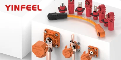
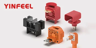
To understand how different connector types—including high-current storage terminal connectors and wall feed-through terminal blocks—are designed to address these failure modes, explore the YINFEEL connector product series.
Preventing connector failures requires moving from reactive maintenance to proactive engineering. Here is a five-step framework:
Step 1: Specify the environment. Match IP rating, plating material, and housing material to your installation environment. Outdoor coastal sites require IP67/IP68 with silver or nickel plating and salt spray testing. Indoor controlled environments may accept lower specifications—but never compromise on contact material.
Step 2: Install with precision. Use calibrated torque wrenches. Follow torque specifications exactly. Avoid overtightening, which warps metal tabs. Ensure proper cable strain relief—no tight bends within 20mm of the cable seal.
Step 3: Inspect systematically. Schedule regular inspections using multiple techniques:
Thermal imaging during peak load to detect hot spots. A temperature deviation above 10°C indicates high resistance
Visual inspection for discoloration (bluing, browning, blackening), melted insulation, and housing cracks
Contact resistance measurement using a micro-ohmmeter. Readings exceeding 0.5 milliohms indicate corrosion or poor crimping
Insulation resistance testing to detect moisture ingress and insulation degradation
Step 4: Monitor continuously. Where feasible, implement real-time monitoring of contact resistance and temperature at critical connection points. Early detection of abnormal increases allows intervention before failure occurs.
Step 5: Replace proactively. Connectors have a finite service life. Plan for periodic replacement based on manufacturer recommendations and inspection data—not after failure occurs.
For guidance on how connector selection varies across residential, commercial, and utility-scale storage applications, visit the YINFEEL current connectors applications page.
Several international standards establish requirements that directly address the failure modes discussed above:
UL 4128 (North America): The energy storage connector safety standard. Requires temperature rise not to exceed 45K when tested at rated current with 90°C RTI cable for 4 hours or until thermal stabilization. This directly addresses overheating failure modes.
IEC 61984 (Global): Defines safety requirements for connectors with rated voltages above 50V up to 1000V and currents up to 125A per contact.
IEC 60512 (Global): Specifies contact resistance and temperature rise test methods for electromechanical components.
T/CNESA 1001-2022 (China): The China Energy Storage Alliance standard for DC power connectors. Specifies temperature rise limits (≤45K), mechanical durability (≥5000 mating cycles), and IP67 protection.
UL 94 V-0: Flammability rating for connector housing materials. Connectors should use flame-retardant PA66 materials to prevent fire propagation.
When selecting connectors, verify that they comply with the relevant standards for your market and application. Compliance is not a guarantee of reliability—but non-compliance is a red flag.
To fully grasp thermal influences on connector performance and the reliability advantages of proper derating, explore our lineup of high-current connectors engineered with verified derating specifications.
Connector failures in energy storage systems are preventable—but prevention starts at the specification stage. Choose connectors with the right materials (silver-plated copper alloy contacts), the right sealing (IP67 or higher), the right locking mechanisms (dual-stage or rotary-lock), and the right certifications (UL 4128, IEC 61984, or equivalent). Install them with precision. Inspect them systematically. And replace them before they fail.
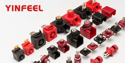
Once you’ve identified the failure modes most relevant to your application environment—whether it’s high vibration, coastal corrosion, or high ambient temperatures—comparing the specific specifications of available connector families becomes the next logical step. You can evaluate high-current storage terminal connectors designed for 60A–600A applications, or explore wall feed-through terminal blocks for cabinet interconnection—each with different materials, sealing levels, and locking mechanisms to match your system’s unique risk profile.
High-Current Connector Derating: How Temperature Affects Your System‘s Safe Operating Range
Understanding UL 4128: Safety Requirements for Energy Storage Connectors
Contact Resistance in High-Current Connectors: Why Milliohms Matter
IP Protection Levels for Energy Storage Connectors: What IP67 Really Means
Connector Plating Materials: Silver vs Tin vs Gold for High-Temperature Environments